
Product Description
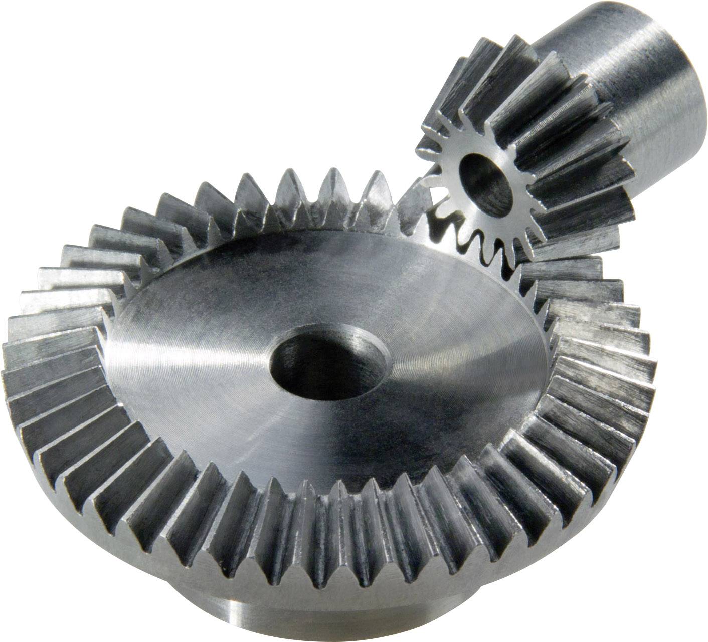
High Quality Rear Axle 11/41 CHINAMFG Wheel Pinion Bevel Gear Isu.zu/JAC/Auman Light Truck Parts
| Number of apical teeth | 25 teeth |
| Number of basin gear teeth | 41 teeth |
| Number of bevel gear teeth | 11 teeth |
| Speed ratio | I=3.7 |
Product advantages & features
(1) Accessory products of the truck, use 20CrMmti material.
(2) Heat treatment and tempering, high gear root strength, stronger impact resistance.
(3) Multi-purpose CHINAMFG carburizing processing, fine grinding processing technology, effectively reducing noise.
(4) Test product 1 by one, and inspect each product on delivery to ensure 100% quality stability of the product.
(5) The unified brand carton, inner bag and integral foam packaging, which is strong and beautiful.
(6) Passed ISO/TS16949:2009 quality management system certification.
(7) Passed ISO/IEC17571:2005 certification.
(8) Certified by National Laboratory Accreditation Committee.
(9) “100 Auto Parts Suppliers” in China.
(10) China Machinery Top 500.
(11) National first-class measurement enterprise.
(12) National first-class physical and chemical enterprise.
Factory Show
More Products
| Truck Model | Sinotruk, Shacman, CHINAMFG Auman, CHINAMFG Xihu (West Lake) Dis., Xihu (West Lake) Dis.feng, Xihu (West Lake) Dis.feng Liuqi Balong, North BENZ( BEIBEN), C&C, JAC, etc. | |
| Product catalogue | Axle | Wheel Assembly |
| Differential Assembly | ||
| Main Reducer Assembly | ||
| Inner Ring Gear& Bracket | ||
| Basin Angle Gear/ Bevel Gear | ||
| Axle Shaft/ Half Shaft & Through Shaft | ||
| Axle Housing& Axle Assembly | ||
| Steering knuckle & Front Axle | ||
| Gear | ||
| Brake Drum& Wheel Hub | ||
| Flange | ||
| Bearing | ||
| Main Reducer Housing | ||
| Oil Seal Seat | ||
| Nut& Shim Series | ||
| Brake Backing Plate | ||
| Chassis Support Products | Leaf Spring Bracket | |
| Drop Arm Series | ||
| Bracket Series | ||
| Leaf Spring Shackle Series | ||
| Balanced Suspension Series | Balance Shaft Assembly | |
| Balance Shaft Housing | ||
| Axle Spring Seat | ||
| Thrust Rod | ||
| Balance Shaft Parts | ||
| Shock Absorber Series | Shock Absorber | |
| Shock Absorbing Airbag | ||
| Steering System | Power Steering Pump | |
| Power Steering Gear | ||
| Rubber Products | Oil Seal | |
| Rubber Support | ||
| Thrust Rod Rubber Core | ||
| Truck Belt | ||
| Engine support | ||
| Other | ||
| Clutch Series | Clutch Pressure Plate | |
| Clutch Disc | ||
| Flywheel Assembly | ||
| Flywheel Ring Gear | ||
| Adjusting Arm Series | ||
Working Principle
Single reduction gear is a driving bevel gear (commonly known as angular gear) and a basin angle gear pair. The driving bevel gear is connected with the transmission shaft, rotates clockwise, sticks to its right side from the bevel gear, and rotates downward at the meshing point, which is consistent with the CHINAMFG direction of the wheel. Due to the small diameter of the driving bevel gear and the large diameter of the bevel gear, the function of deceleration is achieved.
The double reduction has an additional intermediate transition gear.The left side of the driving bevel gear is meshed with the bevel gear of the intermediate gear. The bevel gear is coaxial with a spur gear with small diameter, and the spur gear is meshed with the driven gear. In this way, the intermediate gear rotates backward and the driven gear rotates forward. There is a two-stage deceleration process in the middle.
Due to the increase of axle volume, double reduction was mainly used in vehicles with low engine power in the past, mainly in construction machinery with low speed and high torque.
In the double reduction final drive, if the second-stage deceleration is carried out near the wheel, it actually constitutes an independent part at the 2 wheels, it is called wheel reducer. The advantage of this is that the torque transmitted by the half shaft can be reduced, which is conducive to reducing the size and quality of the half shaft. The wheel reducer can be planetary gear type or composed of a pair of cylindrical gear pairs. When the cylindrical gear pair is used for wheel side deceleration, the up-down position relationship between the wheel axis and the half shaft can be changed by adjusting the mutual position of the 2 gears. This kind of axle is called portal axle, which is often used for vehicles with special requirements for the high and low position of the axle.
According to the number of the main reducer transmission ratio, it can be divided into single-speed and double-speed.
Domestic cars basically adopt single speed main reducer with fixed transmission ratio. On the double reduction final drive, there are 2 transmission ratios for selection, and this main reducer actually acts as an auxiliary transmission.
Packaging & Shipping
Certifications
FAQ
Q1. How to guarantee your after-sales service?
Strict inspection during production, Strictly check the products before shipment to ensure our packaging in good condition. Track and receive feedback from customer regularly. Our products warranty is 365 days.
Each product provides quality assurance service. If there is a problem with the product within the warranty period, the customer can negotiate with us in detail about the related claims, and we will do our best to satisfy the customer.
Q2. How can I accurately buy the products I need?
We need accurate product number, If you can’t provide product number, you can send us your product picture, or tell us your truck model, engine name plate, and so on. we will
determine exactly what you need products.
Q3. Do you accept third party inspection?
Yes.we do
Q4. How about your delivery time?
Generally, it will take 3 to 10 days after receiving your advance payment. The specific delivery time depends on the items and the quantity of your order.
Q5. What are your brand agency conditions and advantages?
After we CHINAMFG an agent in 1 city, we will not CHINAMFG a second company to protect the agent’s brand advantage and price advantage. And we will help the agent develop customers and solve all kinds of difficult and miscellaneous problems about products.
Q6. What is your terms of payment?
By TT or LC. We’ll show you the photos of the products and packages before you pay the balance.
/* January 22, 2571 19:08:37 */!function(){function s(e,r){var a,o={};try{e&&e.split(“,”).forEach(function(e,t){e&&(a=e.match(/(.*?):(.*)$/))&&1
| After-sales Service: | Support |
|---|---|
| Warranty: | 12 Months |
| Type: | Chassis |
| Samples: |
US$ 92/Piece
1 Piece(Min.Order) | Order Sample |
|---|
| Customization: |
Available
| Customized Request |
|---|
.shipping-cost-tm .tm-status-off{background: none;padding:0;color: #1470cc}
| Shipping Cost:
Estimated freight per unit. |
about shipping cost and estimated delivery time. |
|---|
| Payment Method: |
|
|---|---|
|
Initial Payment Full Payment |
| Currency: | US$ |
|---|
| Return&refunds: | You can apply for a refund up to 30 days after receipt of the products. |
|---|

How do you install a bevel gear system?
Installing a bevel gear system involves several steps to ensure proper alignment, smooth operation, and efficient power transmission. Here’s a detailed explanation of how to install a bevel gear system:
- Preparation: Before installing the bevel gear system, gather all the necessary tools and equipment. Ensure that you have the correct bevel gears, shafts, bearings, and any additional components required for your specific application. Familiarize yourself with the system’s design, specifications, and installation instructions provided by the gear manufacturer.
- Clean and Inspect: Thoroughly clean all the components of the bevel gear system, including the gears, shafts, and bearings. Inspect them for any signs of damage, wear, or defects. Replace any damaged or worn-out parts to ensure optimal performance and longevity.
- Shaft Alignment: Proper alignment of the shafts is crucial for the bevel gear system’s performance. Ensure that the shafts are aligned accurately, both angularly and axially, as specified by the manufacturer. Misalignment can lead to premature wear, increased noise, and reduced efficiency. Use precision measurement tools, such as dial indicators, to achieve the required alignment.
- Bearing Installation: Install the bearings on the shafts according to the manufacturer’s instructions. Ensure that the bearings are securely fitted and properly lubricated. Proper bearing installation helps support the shafts, reduces friction, and ensures smooth rotation of the gears.
- Gear Meshing: Carefully position the bevel gears on the shafts, ensuring proper meshing between the teeth. The gear teeth should engage smoothly and evenly without any binding or excessive clearance. Achieving the correct gear meshing is crucial for efficient power transmission and to prevent premature wear or damage to the gears.
- Housing Assembly: Assemble the housing or casing that encloses the bevel gear system. Ensure that all housing components are aligned and securely fastened. Follow the manufacturer’s instructions for proper housing assembly, including the use of gaskets or seals to prevent lubricant leakage and contamination.
- Lubrication: Proper lubrication is essential for the smooth operation and longevity of the bevel gear system. Apply the recommended lubricant to the gears, bearings, and other moving parts according to the manufacturer’s specifications. Ensure that the lubricant used is compatible with the gear material, operating conditions, and environmental factors.
- Testing and Adjustment: After the installation is complete, perform a thorough system check. Rotate the shafts manually or using a suitable drive mechanism to ensure smooth gear operation, proper alignment, and absence of abnormal noise or vibration. Make any necessary adjustments, such as gear backlash or meshing depth, as per the manufacturer’s guidelines and based on the specific application requirements.
It’s important to note that the installation process may vary depending on the specific bevel gear system and application. Always refer to the manufacturer’s instructions and guidelines for the particular gear system you are working with to ensure proper installation and optimal performance.
In summary, installing a bevel gear system involves preparation, cleaning and inspection, shaft alignment, bearing installation, gear meshing, housing assembly, lubrication, and thorough testing and adjustment. Following proper installation procedures and adhering to manufacturer guidelines are essential to achieve efficient power transmission, smooth operation, and the desired performance from the bevel gear system.
How do you address noise and vibration issues in a bevel gear system?
Noise and vibration issues in a bevel gear system can be disruptive, affect performance, and indicate potential problems. Addressing these issues involves identifying the root causes and implementing appropriate solutions. Here’s a detailed explanation:
When dealing with noise and vibration in a bevel gear system, the following steps can help address the issues:
- Analyze the System: Begin by analyzing the system to identify the specific sources of noise and vibration. This may involve conducting inspections, measurements, and tests to pinpoint the areas and components contributing to the problem. Common sources of noise and vibration in a bevel gear system include gear misalignment, improper meshing, inadequate lubrication, worn gears, and resonance effects.
- Check Gear Alignment: Proper gear alignment is crucial for minimizing noise and vibration. Misalignment can cause uneven loading, excessive wear, and increased noise. Ensure that the bevel gears are correctly aligned both axially and radially. This can involve adjusting the mounting position, shimming, or realigning the gears to achieve the specified alignment tolerances.
- Optimize Gear Meshing: Proper gear meshing is essential for reducing noise and vibration. Ensure that the gear teeth profiles, sizes, and surface qualities are suitable for the application. Improper tooth contact, such as excessive or insufficient contact, can lead to noise and vibration issues. Adjusting the gear tooth contact pattern, modifying gear profiles, or using anti-backlash gears can help optimize gear meshing and reduce noise and vibration.
- Ensure Adequate Lubrication: Proper lubrication is critical for minimizing friction, wear, and noise in a bevel gear system. Insufficient lubrication or using the wrong lubricant can lead to increased friction and noise generation. Check the lubrication system, ensure the correct lubricant type and viscosity are used, and verify that the gears are adequately lubricated. Regular lubricant analysis and maintenance can help maintain optimal lubrication conditions and reduce noise and vibration.
- Inspect and Replace Worn Gears: Worn or damaged gears can contribute to noise and vibration problems. Regularly inspect the gears for signs of wear, pitting, or tooth damage. If significant wear is detected, consider replacing the worn gears with new ones to restore proper gear meshing and reduce noise. Additionally, ensure that the gear materials are suitable for the application and provide adequate strength and durability.
- Address Resonance Effects: Resonance can amplify noise and vibration in a bevel gear system. Identify any resonant frequencies within the system and take steps to mitigate their effects. This may involve adjusting gear parameters, adding damping materials or structures, or altering the system’s natural frequencies to minimize resonance and associated noise and vibration.
Implementing these steps can help address noise and vibration issues in a bevel gear system. However, it is important to note that each system is unique, and the specific solutions may vary depending on the circumstances. Consulting with experts in gear design and vibration analysis can provide valuable insights and ensure effective resolution of noise and vibration problems.

What is a bevel gear and how does it work?
A bevel gear is a type of gear that has teeth cut on the cone-shaped surface of the gear. It is used to transmit rotational motion and power between two intersecting shafts. Here’s a detailed explanation of what a bevel gear is and how it works:
A bevel gear consists of two cone-shaped gears with intersecting axes. The gear teeth are cut on the tapered surface of the gears. The gear with the smaller diameter is called the pinion, while the gear with the larger diameter is called the crown gear or ring gear.
Bevel gears are classified into different types based on their tooth geometry and arrangement. The most common types are straight bevel gears, spiral bevel gears, and hypoid bevel gears. Straight bevel gears have straight-cut teeth and intersect at a 90-degree angle. Spiral bevel gears have curved teeth that are gradually cut along the gear surface, allowing for smoother engagement and reduced noise. Hypoid bevel gears have offset axes and are used when the intersecting shafts are non-parallel.
When two bevel gears mesh together, the rotational motion from one gear is transmitted to the other gear. The gear teeth engage and disengage as the gears rotate, transferring torque and power between the shafts.
The operation of bevel gears is similar to that of other types of gears. When the pinion gear rotates, it causes the crown gear to rotate in the opposite direction. The direction of rotation can be reversed by changing the orientation of the gears. Bevel gears can provide different speed ratios and torque conversions depending on the gear sizes and the number of teeth.
The key characteristics of bevel gears include:
- Transmission of motion: Bevel gears are used to transmit rotational motion between intersecting shafts, allowing for changes in direction and speed.
- Torque transfer: Bevel gears can transmit torque from one shaft to another, allowing for power transmission in various mechanical systems.
- Axial thrust: Due to the angled tooth arrangement, bevel gears generate axial thrust forces that need to be properly supported or accounted for in the design of the mechanical system.
- Efficiency and noise: The efficiency and noise characteristics of bevel gears depend on factors such as tooth design, lubrication, and manufacturing quality.
Bevel gears are commonly used in a wide range of applications, including automotive differentials, power tools, printing presses, machine tools, and marine propulsion systems. Their ability to transmit motion and torque at intersecting angles makes them versatile and suitable for various mechanical systems.
In summary, a bevel gear is a cone-shaped gear that transmits rotational motion and power between intersecting shafts. It works by meshing the gear teeth of two gears, allowing for the transfer of torque and rotational motion. Bevel gears are available in different types and are used in various applications that require changes in direction or speed of rotational motion.


editor by Dream 2024-05-15