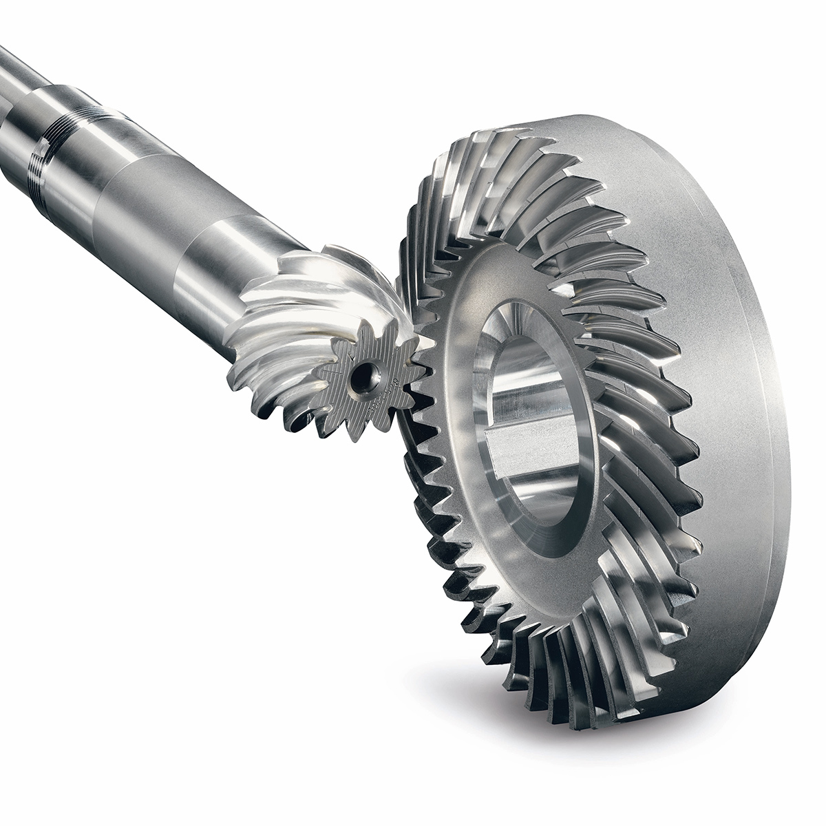
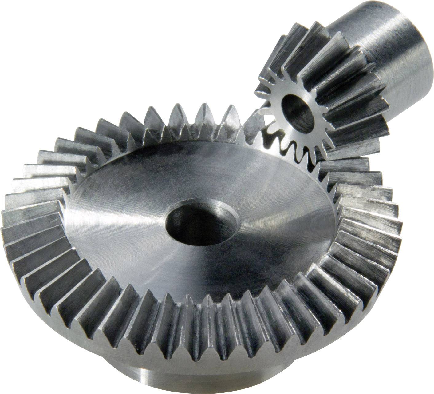
Product Description
We offer OEM metal parts & gears for electornic appliances , mechanical device machine parts through metal injection molding process also powder injection molding.
MIM prcess in each steps :
1. Metal powers option
2. Binders
3. Mixing
4. Molding
5. De-binding
6. Sintering
7. post sintering operation such as polishing
8. Mechanical properties MIM parts
Metal injection molding (MIM) is a metalworking process in which finely-powdered metal is mixed with binder material to create a”feedstock” that is then shaped and solidified using injection molding.The ability to combine several operations into 1 process ensures MIM is successful in saving lead times as well as costs, providing significant benefits to manufacturers. The metal injection molding process might be a green technology due to the significant reduction in wastage compared to “traditional” manufacturing methods.
The window of economic advantage in metal injection molded parts lies in complexity and volume for small-size parts. MIM materials are comparable to metal formed by competing methods, and final products are used in a broad range of industrial, commercial, medical, dental, firearms, aerospace, and automotive applications. Dimensional tolerances of ±0.3% are common and machining is required for closer tolerances .
MIM can produce parts where it is difficult, or even impossible, to efficiently manufacture an item through other means of fabrication. Increased costs for traditional manufacturing methods inherent to part complexity, such as internal/external threads, miniaturization, or identity marking, typically do not increase the cost in a MIM operation due to the flexibility of injection molding.
We offer MIM service with material :
MIM stainless steel 303 , 304 , 316 , 17-4ph
MIM tungsten
MIM copper
custom MIM stainless steel
Metal injection moulding process custom metal parts
The advantages of metal injection molding for metal fabrications :
- Highest degree of design freedom for complex shapes and geometries
- Provides practical economic solutions to increasingly stringent material and product design requirements
- Functional integration of various features, such as lateral drillings, interior and exterior threads and gear teeth.
- Excellent batch to batch repeatability with exceptional process capabilities
- Very high volume production series run on fully-automatic injection molding machines using multi-cavity tools
- Components can be heat and surface treated, plated, welded and soldered
Customized metal parts specification
| Product type | precision components cnc machinery gears , planetary gears , stainless steel gear parts |
| Material | metal , Iron , stainless steel , copper ,carbon steel |
| Process | Metal injection molding , powder metallurgy , stamping |
| Treatment | Polishing , plating ,sand blasting , PVD , coating |
| Tolerance | ±0.3% |
| Drawing format | DWG ,IGS , STP |
| Delivery time | 20 days for mass production |
Custom metal parts
Workshop
/* January 22, 2571 19:08:37 */!function(){function s(e,r){var a,o={};try{e&&e.split(“,”).forEach(function(e,t){e&&(a=e.match(/(.*?):(.*)$/))&&1
| Binder Type: | Acrylic Binder |
|---|---|
| Powder Type: | MIM |
| OEM: | Yes |
| Metal Fabrication: | Stainless Steel , Copper , Aluminum , Iron |
| Metal Gears: | Stainless Steel , Iron |
| Surface Treatment: | Polishing , Plated |
| Samples: |
US$ 2/Piece
1 Piece(Min.Order) | |
|---|
| Customization: |
Available
| Customized Request |
|---|

How do you install a bevel gear system?
Installing a bevel gear system involves several steps to ensure proper alignment, smooth operation, and efficient power transmission. Here’s a detailed explanation of how to install a bevel gear system:
- Preparation: Before installing the bevel gear system, gather all the necessary tools and equipment. Ensure that you have the correct bevel gears, shafts, bearings, and any additional components required for your specific application. Familiarize yourself with the system’s design, specifications, and installation instructions provided by the gear manufacturer.
- Clean and Inspect: Thoroughly clean all the components of the bevel gear system, including the gears, shafts, and bearings. Inspect them for any signs of damage, wear, or defects. Replace any damaged or worn-out parts to ensure optimal performance and longevity.
- Shaft Alignment: Proper alignment of the shafts is crucial for the bevel gear system’s performance. Ensure that the shafts are aligned accurately, both angularly and axially, as specified by the manufacturer. Misalignment can lead to premature wear, increased noise, and reduced efficiency. Use precision measurement tools, such as dial indicators, to achieve the required alignment.
- Bearing Installation: Install the bearings on the shafts according to the manufacturer’s instructions. Ensure that the bearings are securely fitted and properly lubricated. Proper bearing installation helps support the shafts, reduces friction, and ensures smooth rotation of the gears.
- Gear Meshing: Carefully position the bevel gears on the shafts, ensuring proper meshing between the teeth. The gear teeth should engage smoothly and evenly without any binding or excessive clearance. Achieving the correct gear meshing is crucial for efficient power transmission and to prevent premature wear or damage to the gears.
- Housing Assembly: Assemble the housing or casing that encloses the bevel gear system. Ensure that all housing components are aligned and securely fastened. Follow the manufacturer’s instructions for proper housing assembly, including the use of gaskets or seals to prevent lubricant leakage and contamination.
- Lubrication: Proper lubrication is essential for the smooth operation and longevity of the bevel gear system. Apply the recommended lubricant to the gears, bearings, and other moving parts according to the manufacturer’s specifications. Ensure that the lubricant used is compatible with the gear material, operating conditions, and environmental factors.
- Testing and Adjustment: After the installation is complete, perform a thorough system check. Rotate the shafts manually or using a suitable drive mechanism to ensure smooth gear operation, proper alignment, and absence of abnormal noise or vibration. Make any necessary adjustments, such as gear backlash or meshing depth, as per the manufacturer’s guidelines and based on the specific application requirements.
It’s important to note that the installation process may vary depending on the specific bevel gear system and application. Always refer to the manufacturer’s instructions and guidelines for the particular gear system you are working with to ensure proper installation and optimal performance.
In summary, installing a bevel gear system involves preparation, cleaning and inspection, shaft alignment, bearing installation, gear meshing, housing assembly, lubrication, and thorough testing and adjustment. Following proper installation procedures and adhering to manufacturer guidelines are essential to achieve efficient power transmission, smooth operation, and the desired performance from the bevel gear system.

How do you address noise and vibration issues in a bevel gear system?
Noise and vibration issues in a bevel gear system can be disruptive, affect performance, and indicate potential problems. Addressing these issues involves identifying the root causes and implementing appropriate solutions. Here’s a detailed explanation:
When dealing with noise and vibration in a bevel gear system, the following steps can help address the issues:
- Analyze the System: Begin by analyzing the system to identify the specific sources of noise and vibration. This may involve conducting inspections, measurements, and tests to pinpoint the areas and components contributing to the problem. Common sources of noise and vibration in a bevel gear system include gear misalignment, improper meshing, inadequate lubrication, worn gears, and resonance effects.
- Check Gear Alignment: Proper gear alignment is crucial for minimizing noise and vibration. Misalignment can cause uneven loading, excessive wear, and increased noise. Ensure that the bevel gears are correctly aligned both axially and radially. This can involve adjusting the mounting position, shimming, or realigning the gears to achieve the specified alignment tolerances.
- Optimize Gear Meshing: Proper gear meshing is essential for reducing noise and vibration. Ensure that the gear teeth profiles, sizes, and surface qualities are suitable for the application. Improper tooth contact, such as excessive or insufficient contact, can lead to noise and vibration issues. Adjusting the gear tooth contact pattern, modifying gear profiles, or using anti-backlash gears can help optimize gear meshing and reduce noise and vibration.
- Ensure Adequate Lubrication: Proper lubrication is critical for minimizing friction, wear, and noise in a bevel gear system. Insufficient lubrication or using the wrong lubricant can lead to increased friction and noise generation. Check the lubrication system, ensure the correct lubricant type and viscosity are used, and verify that the gears are adequately lubricated. Regular lubricant analysis and maintenance can help maintain optimal lubrication conditions and reduce noise and vibration.
- Inspect and Replace Worn Gears: Worn or damaged gears can contribute to noise and vibration problems. Regularly inspect the gears for signs of wear, pitting, or tooth damage. If significant wear is detected, consider replacing the worn gears with new ones to restore proper gear meshing and reduce noise. Additionally, ensure that the gear materials are suitable for the application and provide adequate strength and durability.
- Address Resonance Effects: Resonance can amplify noise and vibration in a bevel gear system. Identify any resonant frequencies within the system and take steps to mitigate their effects. This may involve adjusting gear parameters, adding damping materials or structures, or altering the system’s natural frequencies to minimize resonance and associated noise and vibration.
Implementing these steps can help address noise and vibration issues in a bevel gear system. However, it is important to note that each system is unique, and the specific solutions may vary depending on the circumstances. Consulting with experts in gear design and vibration analysis can provide valuable insights and ensure effective resolution of noise and vibration problems.

What are the applications of a bevel gear?
A bevel gear finds applications in various industries and mechanical systems where changes in direction or speed of rotational motion are required. Here’s a detailed explanation of the applications of a bevel gear:
- Automotive Industry: Bevel gears are widely used in the automotive industry, particularly in differentials. Differentials are responsible for distributing torque between the driving wheels of a vehicle, allowing them to rotate at different speeds when turning. Bevel gears in differentials transmit power from the engine to the wheels, enabling smooth cornering and improved traction.
- Mechanical Power Transmission: Bevel gears are employed in mechanical power transmission systems to change the direction of rotational motion. They are used in applications such as power tools, machine tools, conveyors, and printing presses. By meshing with other bevel gears or with spur gears, they transmit torque and power efficiently from one shaft to another, accommodating changes in direction and speed.
- Marine Propulsion Systems: Bevel gears are extensively used in marine propulsion systems, including boats and ships. They are commonly found in the propulsion shaft line, where they transmit torque from the engine to the propeller shaft, allowing the vessel to move through water. Bevel gears in marine applications are designed to withstand high loads, resist corrosion, and operate efficiently in harsh environments.
- Aerospace Industry: Bevel gears are utilized in various aerospace applications. They are employed in aircraft landing gear systems, where they transmit torque from the hydraulic motor to extend or retract the landing gear. Bevel gears are also found in helicopter rotor systems, providing the necessary power transmission to rotate the rotor blades.
- Railway Systems: Bevel gears play a crucial role in railway systems, particularly in locomotives and rolling stock. They are used in the transmission systems to transfer power from the engine to the wheels. Bevel gears ensure smooth and efficient power transfer, enabling the train to move forward or backward while negotiating curves on the track.
- Industrial Machinery: Bevel gears are extensively employed in various industrial machinery, such as milling machines, lathes, and industrial robots. They facilitate changes in direction and speed of rotational motion, enabling precise positioning, accurate cutting, and smooth operation of the machinery.
- Mining and Construction Equipment: Bevel gears are used in mining and construction equipment to transfer power and torque in heavy-duty applications. They are found in equipment such as excavators, bulldozers, and crushers, where they provide reliable power transmission in challenging environments.
These are just a few examples of the applications of bevel gears. Their ability to transmit power, change the direction of rotational motion, and accommodate intersecting shafts makes them versatile and suitable for a wide range of industries and mechanical systems.
In summary, bevel gears are extensively utilized in automotive differentials, mechanical power transmission systems, marine propulsion systems, aerospace applications, railway systems, industrial machinery, and mining and construction equipment. Their applications span across industries where changes in direction or speed of rotational motion are essential for efficient and reliable operation.


editor by CX 2024-04-16

