Product Description
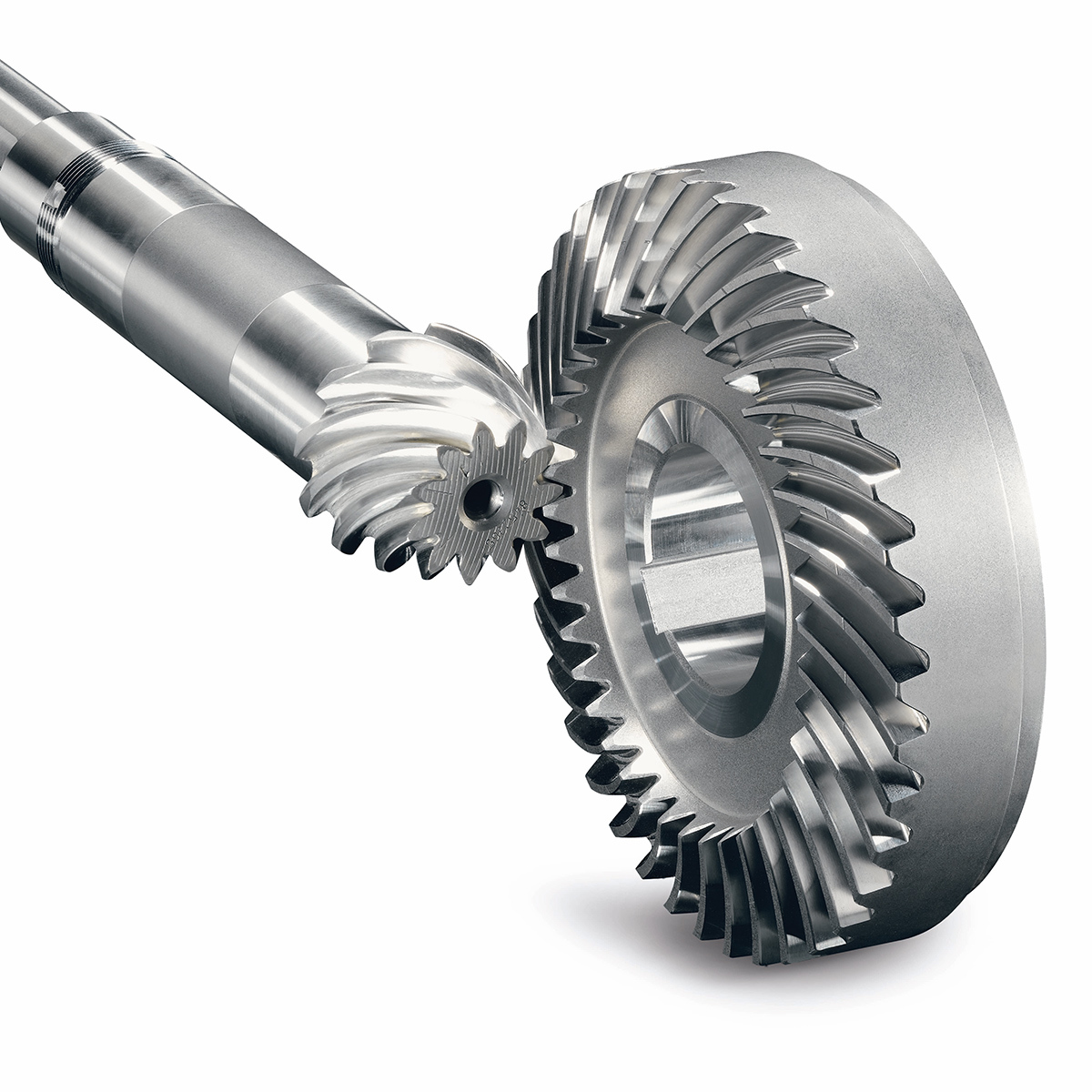
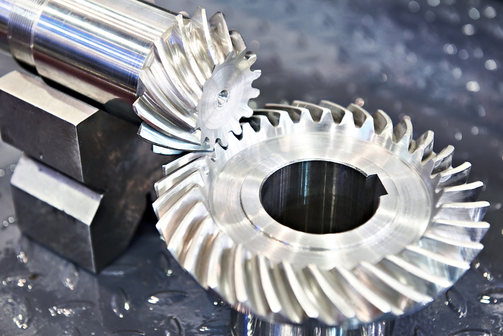
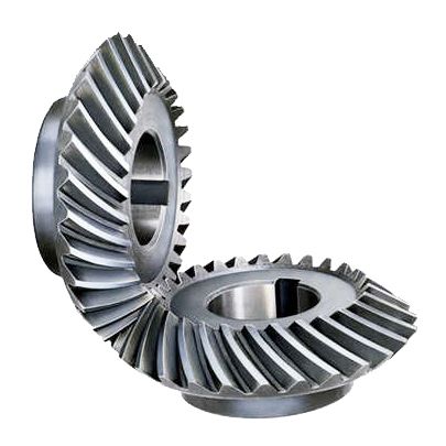
90 degree gearbox hypoid zerol drawing custom air angle grinder cutting machine miter spiral helical spur bevel gears manufacturers
Application of 90 degree gearbox
90 degree gearboxes are used in a wide variety of applications where it is necessary to transmit power from 1 axis to another at a right angle. Some of the most common applications for 90 degree gearboxes include:
- Robotics: 90 degree gearboxes are used in robotics to transmit power from the motor to the robot arm. This allows the robot arm to move in a variety of directions, including up and down, left and right, and CHINAMFG and backward.
- Machine tools: 90 degree gearboxes are used in machine tools to transmit power from the motor to the cutting tool. This allows the cutting tool to move in a variety of directions, including up and down, left and right, and CHINAMFG and backward.
- Conveyor belts: 90 degree gearboxes are used in conveyor belts to transmit power from the motor to the conveyor belt. This allows the conveyor belt to move materials from 1 place to another.
- Wind turbines: 90 degree gearboxes are used in wind turbines to transmit power from the rotor to the generator. This allows the generator to generate electricity.
- Electric vehicles: 90 degree gearboxes are used in electric vehicles to transmit power from the motor to the wheels. This allows the electric vehicle to move CHINAMFG and backward.
90 degree gearboxes are a versatile and reliable component that can be used in a wide variety of applications. They are characterized by their ability to transmit power from 1 axis to another at a right angle, which makes them ideal for applications where space is limited or where the need for compactness is a priority.
Here are some of the advantages and disadvantages of 90 degree gearboxes:
Advantages:
- Compact size
- High efficiency
- Low noise
- Long life
Disadvantages:
- Expensive
- Complex design
- Can be difficult to maintain
Overall, 90 degree gearboxes are a versatile and reliable component that can be used in a wide variety of applications. They are characterized by their compact size, high efficiency, and low noise. However, they can be expensive and complex to design and maintain.
/* January 22, 2571 19:08:37 */!function(){function s(e,r){var a,o={};try{e&&e.split(“,”).forEach(function(e,t){e&&(a=e.match(/(.*?):(.*)$/))&&1
| Application: | Motor, Electric Cars, Motorcycle, Machinery, Marine, Toy, Agricultural Machinery, Car |
|---|---|
| Hardness: | Hardened Tooth Surface |
| Gear Position: | Internal Gear |
| Manufacturing Method: | Cast Gear |
| Toothed Portion Shape: | Spur Gear |
| Material: | Stainless Steel |
| Samples: |
US$ 9999/Piece
1 Piece(Min.Order) | |
|---|

How do you install a bevel gear system?
Installing a bevel gear system involves several steps to ensure proper alignment, smooth operation, and efficient power transmission. Here’s a detailed explanation of how to install a bevel gear system:
- Preparation: Before installing the bevel gear system, gather all the necessary tools and equipment. Ensure that you have the correct bevel gears, shafts, bearings, and any additional components required for your specific application. Familiarize yourself with the system’s design, specifications, and installation instructions provided by the gear manufacturer.
- Clean and Inspect: Thoroughly clean all the components of the bevel gear system, including the gears, shafts, and bearings. Inspect them for any signs of damage, wear, or defects. Replace any damaged or worn-out parts to ensure optimal performance and longevity.
- Shaft Alignment: Proper alignment of the shafts is crucial for the bevel gear system’s performance. Ensure that the shafts are aligned accurately, both angularly and axially, as specified by the manufacturer. Misalignment can lead to premature wear, increased noise, and reduced efficiency. Use precision measurement tools, such as dial indicators, to achieve the required alignment.
- Bearing Installation: Install the bearings on the shafts according to the manufacturer’s instructions. Ensure that the bearings are securely fitted and properly lubricated. Proper bearing installation helps support the shafts, reduces friction, and ensures smooth rotation of the gears.
- Gear Meshing: Carefully position the bevel gears on the shafts, ensuring proper meshing between the teeth. The gear teeth should engage smoothly and evenly without any binding or excessive clearance. Achieving the correct gear meshing is crucial for efficient power transmission and to prevent premature wear or damage to the gears.
- Housing Assembly: Assemble the housing or casing that encloses the bevel gear system. Ensure that all housing components are aligned and securely fastened. Follow the manufacturer’s instructions for proper housing assembly, including the use of gaskets or seals to prevent lubricant leakage and contamination.
- Lubrication: Proper lubrication is essential for the smooth operation and longevity of the bevel gear system. Apply the recommended lubricant to the gears, bearings, and other moving parts according to the manufacturer’s specifications. Ensure that the lubricant used is compatible with the gear material, operating conditions, and environmental factors.
- Testing and Adjustment: After the installation is complete, perform a thorough system check. Rotate the shafts manually or using a suitable drive mechanism to ensure smooth gear operation, proper alignment, and absence of abnormal noise or vibration. Make any necessary adjustments, such as gear backlash or meshing depth, as per the manufacturer’s guidelines and based on the specific application requirements.
It’s important to note that the installation process may vary depending on the specific bevel gear system and application. Always refer to the manufacturer’s instructions and guidelines for the particular gear system you are working with to ensure proper installation and optimal performance.
In summary, installing a bevel gear system involves preparation, cleaning and inspection, shaft alignment, bearing installation, gear meshing, housing assembly, lubrication, and thorough testing and adjustment. Following proper installation procedures and adhering to manufacturer guidelines are essential to achieve efficient power transmission, smooth operation, and the desired performance from the bevel gear system.

How do you calculate the efficiency of a bevel gear?
To calculate the efficiency of a bevel gear, you need to compare the power input to the gear with the power output and account for any losses in the gear system. Here’s a detailed explanation of the calculation process:
The efficiency of a bevel gear can be calculated using the following formula:
Efficiency = (Power output / Power input) x 100%
Here’s a step-by-step breakdown of the calculation:
- Calculate the Power Input: Determine the power input to the bevel gear system. This can be obtained by multiplying the input torque (Tin) by the input angular velocity (ωin), using the formula:
- Calculate the Power Output: Determine the power output from the bevel gear system. This can be obtained by multiplying the output torque (Tout) by the output angular velocity (ωout), using the formula:
- Calculate the Efficiency: Divide the power output by the power input and multiply by 100% to obtain the efficiency:
Power input = Tin x ωin
Power output = Tout x ωout
Efficiency = (Power output / Power input) x 100%
The efficiency of a bevel gear represents the percentage of input power that is effectively transmitted to the output, considering losses due to factors such as friction, gear meshing, and lubrication. It is important to note that the efficiency of a bevel gear system can vary depending on various factors, including gear quality, alignment, lubrication condition, and operating conditions.
When calculating the efficiency, it is crucial to use consistent units for torque and angular velocity. Additionally, it’s important to ensure that the power input and output are measured at the same point in the gear system, typically at the input and output shafts.
Keep in mind that the calculated efficiency is an approximation and may not account for all the losses in the gear system. Factors such as bearing losses, windage losses, and other system-specific losses are not included in this basic efficiency calculation. Actual efficiency can vary based on the specific design and operating conditions of the bevel gear system.
By calculating the efficiency, engineers can evaluate the performance of a bevel gear and make informed decisions regarding gear selection, optimization, and system design.

What are the benefits of using a bevel gear mechanism?
Using a bevel gear mechanism offers several benefits in various applications. Here’s a detailed explanation of the advantages of using a bevel gear mechanism:
- Change in Direction: Bevel gears are designed to transmit rotational motion between intersecting or non-parallel shafts. They enable a change in direction of motion, allowing the rotary power to be transmitted efficiently at different angles, such as 90 degrees or more. This capability is particularly useful in applications where space constraints or specific mechanical arrangements require a change in direction.
- Speed Reduction or Increase: Bevel gears can be used to achieve speed reduction or increase between the input and output shafts. By selecting bevel gears with different tooth counts, the rotational speed can be adjusted according to the desired output requirements. This feature is beneficial in applications where different speeds are needed for specific operations or to match the requirements of the driven equipment.
- Compact Design: Bevel gears offer a compact design that allows for efficient power transmission in applications with limited space. The intersecting shafts and compact arrangement of the gear teeth enable the transmission of torque and motion in a more confined area compared to other types of gear mechanisms.
- High Torque Transmission: Bevel gears are capable of transmitting high torque loads. The meshing of the gear teeth provides a strong and reliable connection, allowing for the efficient transfer of power even in heavy-duty applications. This makes bevel gears suitable for applications that require the transmission of substantial torque, such as in automotive differentials, industrial machinery, and mining equipment.
- Versatility: Bevel gears are versatile and can be designed to accommodate various operating conditions and requirements. They can be manufactured with different tooth profiles, such as straight-cut, spiral, or zerol, to optimize performance based on factors like noise reduction, load capacity, and efficiency. Additionally, bevel gears can be made from different materials, allowing them to withstand different environmental conditions and requirements.
- Smooth and Quiet Operation: The tooth geometry of spiral bevel gears provides smoother and quieter operation compared to straight-cut gears. The gradual engagement of the curved teeth reduces noise, vibration, and shock during gear meshing, resulting in quieter operation and improved overall system performance. This makes bevel gears suitable for applications where noise reduction is a critical consideration.
- Wide Range of Applications: Bevel gears find applications in various industries and systems where changes in direction, speed, and torque transmission are required. They are used in automotive differentials, marine propulsion systems, industrial machinery, robotics, aerospace systems, and more. The versatility and adaptability of bevel gears make them suitable for a wide range of applications across different sectors.
In summary, using a bevel gear mechanism provides benefits such as change in direction, speed adjustment, compact design, high torque transmission, versatility, smooth and quiet operation, and suitability for a wide range of applications. These advantages make bevel gears a preferred choice in numerous industries and systems that require efficient and reliable power transmission.


editor by Dream 2024-05-09

