Product Description
Product Description
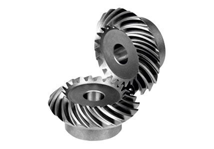
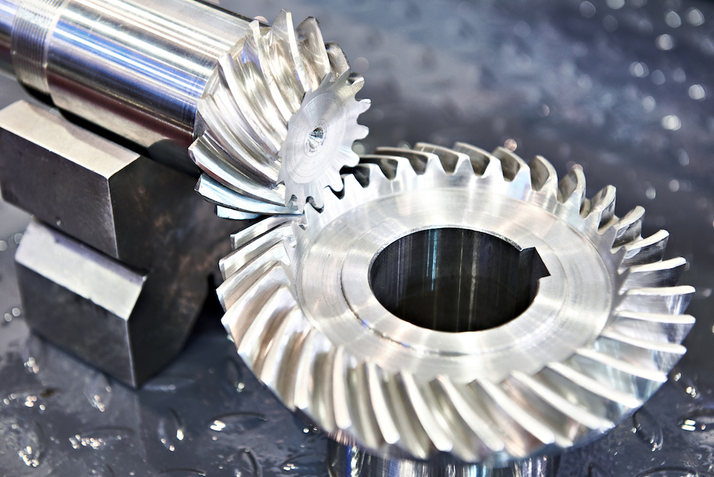
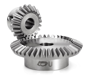
Spiral Bevel Gear Features:
1) Material: 42CrMo, 20CrMnMo, 20Cr2Ni4, 35CrMo, 20CrMnTi and
Other high intensity alloy steel
2) Tooth flank carburization and nitrification, with rigidity of HRC60-62
3) Gear precision: Grade V
4)Precise measurement and surface finishes are available
5)High dense alloy or other materials is also available
6)custormer’s drawing and samples are welcome
Bevel Gears Process:
ISO9001: 2008 Quality Certification:
http://baoxincz
Detailed Photos
Production Profile
About Us
About Us
As a company of industries and trading integration with ISO 9001-2008 Certificate, HangZhou CHINAMFG Metallurgy Equipment Manufacturing Co., Ltd. Has been in manufacturing material handling equipment parts for many years, with professional experience.
Our Service:
If you are interested in any of our products, please contact me freely! Warmly Welcomed your visit to our factory in China, OEM service will be ok.
Customer Visiting
Certifications
Packaging & Shipping
/* January 22, 2571 19:08:37 */!function(){function s(e,r){var a,o={};try{e&&e.split(“,”).forEach(function(e,t){e&&(a=e.match(/(.*?):(.*)$/))&&1
| Application: | Motor, Motorcycle, Machinery |
|---|---|
| Hardness: | HRC 60-65 |
| Gear Position: | External Gear |
| Manufacturing Method: | Cut Gear |
| Toothed Portion Shape: | Bevel Wheel |
| Material: | Lron |
| Customization: |
Available
| Customized Request |
|---|

How do you prevent backlash and gear play in a bevel gear mechanism?
In a bevel gear mechanism, preventing backlash and gear play is essential for ensuring accurate and efficient power transmission. Backlash refers to the clearance or free movement between the mating teeth of gears, resulting in a brief loss of motion or a dead zone when changing direction. Here are some methods to prevent backlash and minimize gear play in a bevel gear mechanism:
- Precision Manufacturing: High-precision manufacturing processes are crucial for minimizing backlash and gear play in bevel gears. Accurate machining of gear teeth and precise control of tooth dimensions, profiles, and alignment help achieve tight meshing between the gears, reducing the clearance and backlash. Modern manufacturing techniques, such as CNC machining and gear grinding, can ensure the desired level of precision and minimize gear play.
- Proper Gear Design: The design of the bevel gears can influence the amount of backlash and gear play. An optimized gear design, including suitable tooth profiles, pressure angles, and tooth contact patterns, can help distribute the load evenly and minimize the clearance between the mating teeth. By carefully considering gear design parameters, designers can reduce backlash and improve gear meshing characteristics.
- Preload or Pre-Tension: Applying a preload or pre-tension to the bevel gears can help minimize backlash and gear play. This involves applying a slight force or tension to the gears, forcing them to maintain contact and reducing the clearance between the teeth. Preload can be achieved through various methods, such as using spring mechanisms, shimming, or adjusting the mounting position of the gears.
- Backlash Compensation: Backlash compensation methods aim to minimize the effects of backlash and gear play by introducing mechanisms or techniques that compensate for the clearance. One common approach is to use anti-backlash gears, which have special tooth profiles or arrangements that reduce or eliminate clearance between the mating teeth. Another method is to incorporate backlash compensation devices, such as spring-loaded mechanisms or adjustable shims, that actively reduce the backlash during operation.
- Tight Control of Tolerances: Maintaining tight tolerances during the manufacturing and assembly processes is critical for minimizing backlash and gear play. Close control of dimensions, alignment, and clearances ensures proper gear meshing and reduces the possibility of excessive play. Quality control measures, such as inspection, testing, and verification of gear dimensions, can help ensure that the gears meet the specified tolerances.
- Regular Maintenance: Regular maintenance practices, including inspection, lubrication, and adjustment, are essential for preventing and minimizing backlash and gear play over time. Periodic checks for wear, misalignment, and proper lubrication can help identify and rectify any issues that may contribute to increased backlash. Timely maintenance and replacement of worn or damaged gears can help maintain optimal gear meshing and minimize play.
By implementing these methods, it is possible to significantly reduce backlash and gear play in a bevel gear mechanism, resulting in improved accuracy, efficiency, and longevity of the gear system.

How do you calculate the efficiency of a bevel gear?
To calculate the efficiency of a bevel gear, you need to compare the power input to the gear with the power output and account for any losses in the gear system. Here’s a detailed explanation of the calculation process:
The efficiency of a bevel gear can be calculated using the following formula:
Efficiency = (Power output / Power input) x 100%
Here’s a step-by-step breakdown of the calculation:
- Calculate the Power Input: Determine the power input to the bevel gear system. This can be obtained by multiplying the input torque (Tin) by the input angular velocity (ωin), using the formula:
- Calculate the Power Output: Determine the power output from the bevel gear system. This can be obtained by multiplying the output torque (Tout) by the output angular velocity (ωout), using the formula:
- Calculate the Efficiency: Divide the power output by the power input and multiply by 100% to obtain the efficiency:
Power input = Tin x ωin
Power output = Tout x ωout
Efficiency = (Power output / Power input) x 100%
The efficiency of a bevel gear represents the percentage of input power that is effectively transmitted to the output, considering losses due to factors such as friction, gear meshing, and lubrication. It is important to note that the efficiency of a bevel gear system can vary depending on various factors, including gear quality, alignment, lubrication condition, and operating conditions.
When calculating the efficiency, it is crucial to use consistent units for torque and angular velocity. Additionally, it’s important to ensure that the power input and output are measured at the same point in the gear system, typically at the input and output shafts.
Keep in mind that the calculated efficiency is an approximation and may not account for all the losses in the gear system. Factors such as bearing losses, windage losses, and other system-specific losses are not included in this basic efficiency calculation. Actual efficiency can vary based on the specific design and operating conditions of the bevel gear system.
By calculating the efficiency, engineers can evaluate the performance of a bevel gear and make informed decisions regarding gear selection, optimization, and system design.

How do bevel gears differ from other types of gears?
Bevel gears have distinct characteristics that set them apart from other types of gears. Here’s a detailed explanation of how bevel gears differ from other gears:
1. Tooth Geometry: Bevel gears have teeth cut on the cone-shaped surface of the gears, whereas other types of gears, such as spur gears and helical gears, have teeth cut on cylindrical surfaces. The tooth geometry of bevel gears allows them to accommodate intersecting shafts and transmit rotational motion at different angles.
2. Axis Orientation: Bevel gears have intersecting axes, meaning the shafts they are mounted on intersect each other. In contrast, other types of gears typically have parallel or skewed axes. The intersecting axis of bevel gears allows for changes in direction and allows for power transmission between shafts that are not in a straight line.
3. Types of Bevel Gears: Bevel gears come in different variations, including straight bevel gears, spiral bevel gears, and hypoid bevel gears. Straight bevel gears have straight-cut teeth and intersect at a 90-degree angle. Spiral bevel gears have curved teeth that are gradually cut along the gear surface, providing smoother engagement and reduced noise. Hypoid bevel gears have offset axes and are used when the intersecting shafts are non-parallel. Other types of gears, such as spur gears and helical gears, also have their own variations but do not typically involve intersecting axes.
4. Direction of Motion: Bevel gears can change the direction of rotational motion between intersecting shafts. Depending on the orientation of the gears, the direction of rotation can be reversed. This capability makes bevel gears suitable for applications where changes in direction are required. In contrast, other gears, such as spur gears and helical gears, transmit motion in a specific direction along parallel or skewed axes.
5. Load Distribution: Bevel gears distribute loads differently compared to other gears. Due to the conical shape of the gears, the contact area between the teeth changes as the gears rotate. This can result in varying load distribution along the gear teeth. Other gears, such as spur gears and helical gears, have a consistent load distribution along their teeth due to their cylindrical shape.
6. Applications: Bevel gears are commonly used in applications where changes in direction or speed of rotational motion are required, such as automotive differentials, marine propulsion systems, and power transmission systems. Other types of gears, such as spur gears and helical gears, are more commonly used in applications where parallel or skewed shafts are involved and changes in direction are not necessary.
While bevel gears have their unique characteristics, it’s important to note that different types of gears have their own advantages and applications. The selection of the appropriate gear type depends on factors such as the application requirements, operating conditions, space limitations, and load considerations.
In summary, bevel gears differ from other types of gears in terms of tooth geometry, axis orientation, types of variations available, direction of motion, load distribution, and applications. Their ability to accommodate intersecting shafts and change the direction of rotational motion makes them suitable for specific applications where other types of gears may not be as effective.


editor by Dream 2024-05-14

